
What Is a Remotely Operated Inline Isolation Tool?—Part 2
F. SOENDERVIK, Pipeline Ultraisolation Group (PLUG), Houston, Texas
In Part 1 of this series (published in the June issue of Pipeline & Gas Journal), the inline isolation tool (IIT) established in the 1990s was introduced, with an overview of the process from initial customer requirements through engineering, manufacturing and delivery. In this part, the focus shifts to the tool's distinctive functional capabilities and principal components.
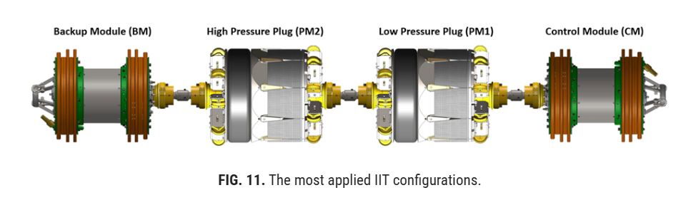
The IIT is a modular system architecture that can be configured in multiple ways depending on project-specific requirements. Although several design approaches are possible, the most commonly applied configurations are presented in this article.
The control module (CM)
The CM serves as the primary command, control and power unit of the IIT. It houses the components necessary to monitor, energize and operate the plug modules in accordance with the defined operating sequence. These components typically include the hydraulic pump, hydraulic fluid reservoir, battery system, control electronics, pressure sensors, temperature sensors, tracking antenna and contingency release system.
The CM also provides the drive required to move the tool through the pipeline during deployment and recovery (FIG. 11).
The backup module (BM)
The BM serves as a secondary power supply and monitoring unit within the IIT. It includes a backup battery pack, redundant pressure and temperature sensors, a tracking antenna and a secondary contingency release system.
In addition, the BM provides the drive required to move the tool through the pipeline during deployment and recovery. The specific configuration of this module can vary considerably depending on vendor design philosophy, system redundancy requirements and project-specific operational criteria.
The plug module (PM)
The PM is the section of the tool responsible for anchoring and sealing against the pipe wall. It creates the mechanical grip and pressure-tight seal required for isolation (FIG. 12).
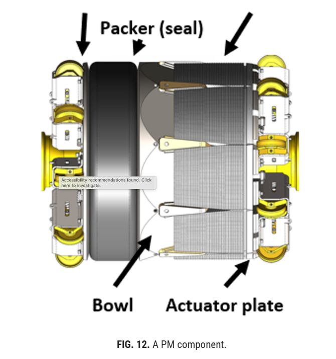
The PM consists of the following main components:
- Actuator plate
- Piston
- Packer/seal
- Bowl
- Spring
- Grips/slips
- Pressure plate
The dummy pig
A dummy pig is primarily used for two purposes: to increase the annulus volume or overall tool length and, in some configurations, to serve as a replacement for the BM. Its use is particularly relevant in liquid isolation applications, where annulus pressure can be challenging to keep stable, especially when the pipeline is exposed to environmental heating such as direct sunlight.
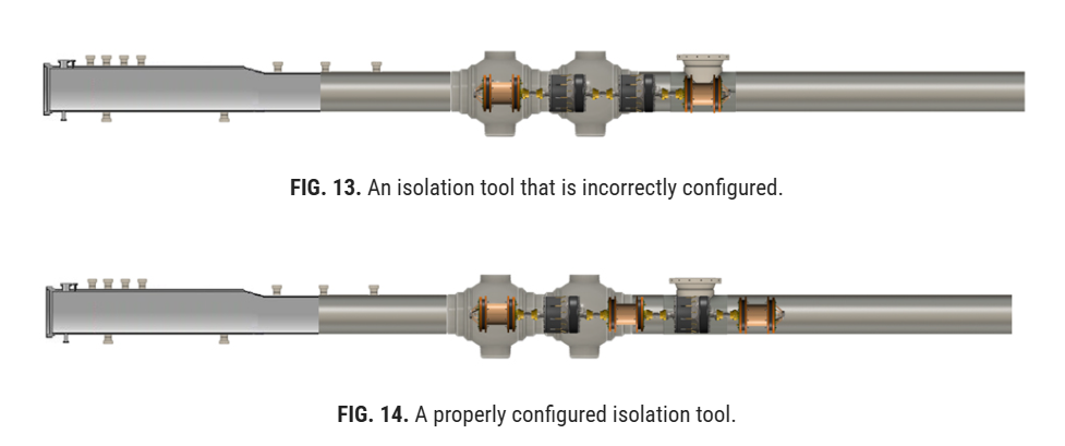
Depending on pipeline geometry and component spacing, it may be necessary to increase the overall tool length to ensure that the pigging module maintains at least one set of pigging discs fully engaged with the pipe bore at all times. This is required to provide sufficient driving force during pigging. If adequate disc engagement is not maintained, the tool may stall, resulting in pigging difficulties or loss of propulsion.
In some configurations, the BM may also be replaced with a dummy pig to accommodate a third-party customer-supplied pinger, where required by the project.
FIG. 13 shows an isolation tool that is incorrectly configured and is therefore likely to stall, as both pigging drive modules are positioned within a cavity where the discs are not engaged with the pipe wall. FIG. 14 shows a properly configured isolation tool, in which the front pigging discs are fully engaged with the pipe wall to provide reliable tool drive during pigging.
Double block
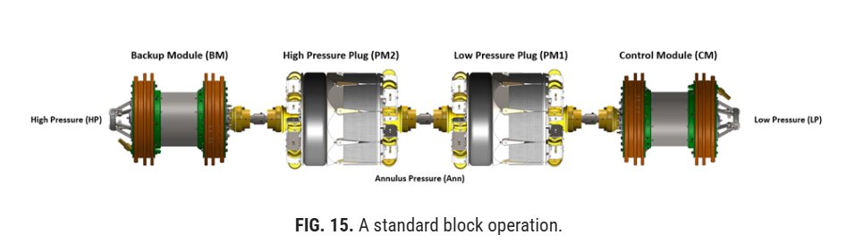
A standard double block configuration uses two plug modules to create two independent sealing barriers inside the pipeline. Each PM anchors and seals against the pipe wall, forming a controlled isolation zone between the high-pressure side and the low-pressure work area.
The purpose of the double block setup is to provide a higher level of safety than a single barrier. If one seal were to leak, the second PM remains in place as an additional barrier. The space between the two PMs, called the annulus, is monitored for pressure changes during the isolation period. Any increase or decrease in annulus pressure can indicate a potential seal issue, allowing the operator to take corrective action before work continues.
In a standard double block operation, both PMs are set against the pipe wall, and the annulus pressure is monitored to confirm that the isolation is stable. Once the system has passed the required holding period, typically 4 hrs, an isolation certificate is issued, and pipework can begin on the low-pressure side.
This configuration is commonly used when a safe, verified isolation is required for maintenance, valve replacement, flange work or other pipeline repair activities (FIG. 15).
Double block with hydrotest module
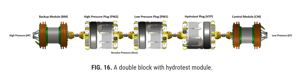
The double block with hydrotest module uses two PMs to provide double isolation, with an additional third PM installed in the opposite direction. This third PM is flipped 180° so it can apply pressure toward the low-pressure side of the isolation.
The purpose of the hydrotest module is not to create the primary isolation, but to allow pressure testing of the pipe section, valve, flange or other component that has been replaced or repaired on the low-pressure side. After the repair work is completed, the hydrotest module can be used to pressurize the test section and verify that the new installation is holding pressure before the isolation tool is unset and removed.
This configuration provides a controlled way to confirm the integrity of the completed work while the pipeline remains safely isolated by the double block system (FIG. 16).
Single block
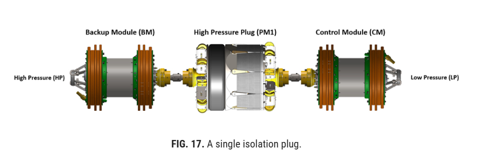
A single isolation plug configuration uses one PM to isolate a section of pipeline from the live system. The PM is positioned at the required location and set against the pipe wall. Once set, the grips secure the tool in place while the packer forms a pressure-tight seal inside the pipe.
This configuration is normally used in conjunction with a proven working valve. In this arrangement, the isolation plug provides the primary isolation, while the closed valve provides an additional level of security. The valve is typically confirmed to be functional before the plug is installed, allowing the two components to work together to create a safe work environment.
A single isolation plug is commonly used for maintenance, inspection, valve work, flange work, minor pipeline repairs or applications where a full double block tool will not fit due to pipe restrictions (FIG. 17).
Before discussing the inline isolation process in detail, it is necessary to define the principal tool features and associated terminology used throughout this work. Key terms include self-lock, contingency release system, structural test, factory acceptance test (FAT), system integration test (SIT), CM, PM, BM, zero-energy zone, hydraulic lock, double block, extreme low frequency (ELF) and stress calculations. Each of these terms is explained individually in the sections that follow.
Self-lock
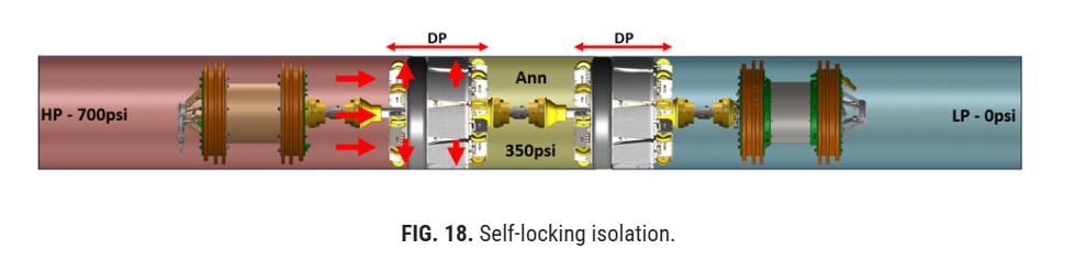
Self-lock is defined as the minimum differential pressure (DP) necessary to maintain sealing integrity and mechanical isolation in the absence of applied hydraulic pressure.
Under self-lock conditions, the axial load generated by the DP acting across the plug module must be sufficient to overcome the opposing packer reaction forces and internal spring forces, without any hydraulic assistance from the actuation cylinder. Consequently, the isolation state does not depend on sustained hydraulic pressure or on the continued engagement of auxiliary hydraulic or mechanical locking components.
This operating principle provides an inherent fail-safe characteristic, as the isolation is maintained by system pressure and plug geometry rather than by an externally maintained actuation force. For this reason, self-locking isolation is considered one of the highest-integrity and safest methods of pipeline isolation (FIG. 18).
Hydraulic lock
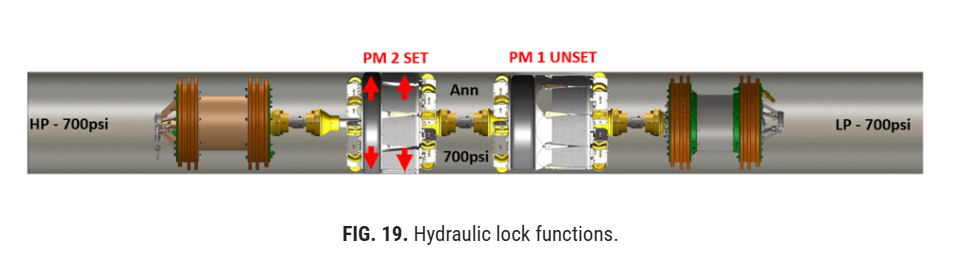
Hydraulic lock is the condition in which the hydraulic set pressure within the PM actuation circuit is trapped and maintained after tool activation by a hydraulic pump and associated isolation valve(s).
This retained hydraulic pressure holds the actuator in the set position and provides support to the locking and sealing elements when the DP across the tool is below the self-lock threshold. Accordingly, hydraulic lock functions as a secondary retention mechanism, whereas self-lock is achieved when pipeline DP alone is sufficient to maintain the isolation (FIG. 19).
Pigging valve
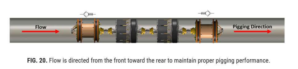
The CM, BM and dummy pig are all equipped with a pigging valve. The function of the pigging valve is to allow flow to pass through the module during tool movement through the pipeline.
In principle, the pigging valve operates as a check-valve-type flow path that helps establish the correct driving condition across the tool.
The purpose of this arrangement is to promote pulling of the tool through the line rather than pushing it from behind, as a purely pushing condition may lead to unstable pigging behavior or reduced drive efficiency. During pumping, flow entering from the rear is allowed to pass through the rear module so the driving pressure can act more effectively on the forward module, thereby pulling the tool through the pipeline.
The same principle applies during reverse movement, where flow is directed from the front toward the rear to maintain proper pigging performance in the opposite direction. This operating principle is shown in FIG. 20.
Double block and monitor
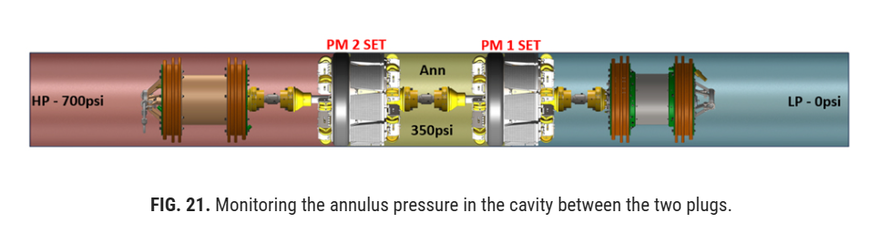
With the current industry emphasis on safety and risk reduction, most customers require a double-block configuration, meaning the tool is equipped with two seals. Each PM is designed such that it can independently withstand the full DP without overstressing the pipeline. Because the two PMs function independently of one another, they each serve as a fully independent isolation barrier. This arrangement is widely regarded as one of the highest-integrity and safest methods of inline isolation currently available. The integrity of the isolation system is verified by monitoring the annulus pressure in the cavity between the two plugs (FIG. 21).
ELF
The tool operates within the 3 Hz–30 Hz frequency range, commonly defined as the ELF band. Operation in this frequency range enables signal transmission through the steel wall of the pipeline, thereby supporting communication and tracking during tool deployment and operation.
Stress calculations
Each project presents a unique set of operating conditions and therefore requires a job-specific stress assessment. Before a quotation can be prepared, the customer must provide the pipeline outside diameter (OD), wall thickness (WT), operating pressure and pipe grade so the engineer can evaluate the stresses induced by the PMs.
If the calculated stresses remain within the allowable limits, no additional mitigation measures are required. However, if the predicted stresses exceed the allowable limits defined by applicable codes, standards or project requirements, mitigation is necessary. Typical mitigation measures include reducing the pipeline operating pressure or installing external reinforcement clamps.
Contingency release system
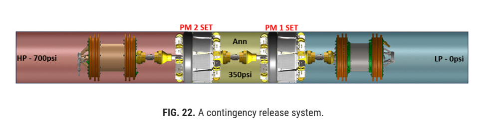
Mechanical, hydraulic and electronic failures may occur during tool deployment or while the tool is in the set condition. To mitigate this risk, IITs are equipped with a contingency release system. The system is a dedicated recovery function used when the tool is set and failure within one or more onboard systems prevents normal operation or standard release procedures. In such circumstances, the system provides an alternative method for releasing the tool and restoring retrievability. FIG. 22 shows a tool in the set position actively isolating pipeline pressure that has experienced an unforeseen issue requiring activation of the contingency release system following completion of the client's work.
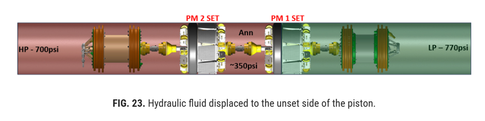
After completion of the pipework, the low-pressure side is pressurized to approximately 10% of the high-pressure side. This pressure triggers the onboard contingency release system, causing the hydraulic circuits to be equalized. Hydraulic fluid is then displaced to the unset side of the piston by the force generated by the internal spring, initiating the release sequence. This operation typically requires 5 min–10 min to complete (FIG. 23).
After the required waiting period, the tool is fully unset and can be pigged back to the launcher or receiver for recovery (FIG. 24).
Zero-energy zone
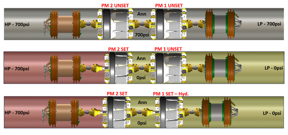
Certain customers require verification that the annulus is in a zero-energy condition. This condition is established by first setting the second PM and applying the required DP across it to verify seal integrity. The first PM is then set while the annulus is maintained at zero pressure or vented to the required project condition.
Once both PMs are set, the isolation integrity is verified and monitored through the agreed project monitoring measures, including the annulus, high-pressure side, low-pressure side and relevant plug hydraulic status indicators. This provides continuous confirmation that the isolation remains stable throughout the work period.
This approach is consistent with the general principles of DNV-RP-F113, which requires independent and tested barriers, monitoring of the pressure between the barriers, documented monitoring sensitivity and continued monitoring throughout the isolation period. For systems using hydraulic set circuits as part of monitoring, these should be treated as additional verification measures and documented in the project-specific procedure rather than as a replacement for annulus pressure monitoring (FIG. 25).
Structural test
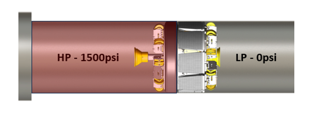
A structural test is the initial qualification test performed on a PM after first-time assembly. As the name implies, the purpose of the test is to verify the structural integrity of the module at its maximum design load. In addition to the rated load condition, an extra 50% safety margin is typically applied, corresponding to a 1.5 safety factor. For example, if the tool is rated for 1,000 psi, the structural test would be conducted at 1,500 psi.
During the test, the tool is installed in a representative pipe section and subjected to the specified pressure for a predetermined hold period established by the responsible engineer. Throughout the test, pressure, temperature and strain data are recorded using a data logger for subsequent analysis. The resulting dataset provides the baseline reference for future stress assessments and job-specific structural evaluations (FIG. 26).
Systems integration test (SIT)
Following completion of the structural test, the tool is fully assembled and installed in a representative test pipe for an SIT. The purpose of the SIT is to verify the integrated performance of the complete system, including mechanical functions, software operation, electronic systems and hydraulic actuation. Because all major subsystems are evaluated under representative operating conditions, this is an extensive test program and may require one to two days to complete.
Prior to the SIT, each component and subsystem undergoes staged qualification testing to confirm individual functionality. The SIT then serves as the final integrated validation of the complete plug train, demonstrating its ability to track, control and isolate pipeline pressure as intended. Successful completion of the SIT also verifies the reliability of the contingency unset function and confirms that battery capacity meets or exceeds operational requirements. Upon satisfactory completion of the test program, the tool is considered qualified for market release. If any errors or failures are identified during testing, the deficiencies must be corrected and the SIT repeated before qualification can be granted (FIG. 27).

Factory acceptance test (FAT)
Following the final assembly of the tool for a specific project, the final qualification step is the FAT. The purpose of the FAT is to validate tool performance under conditions that replicate, as closely as practicable, the operating environment expected in the target pipeline. In some cases, the customer provides a section of pipe matching the actual project specification; otherwise, a test pipe is selected that closely represents the relevant project requirements.
For the FAT, the tool is typically fitted with support discs and minimal wheel assemblies to facilitate handling during the test. The final operational discs and wheel arrangements are installed after completion of the FAT. The customer is normally invited to witness the test in person; when attendance is not possible, remote observation is generally provided through a live online connection. During the test, video, tool data and data logger outputs are displayed in real time. In certain cases, the customer may also require an independent third-party witness.
After completion of the test, which typically lasts approximately 4 hrs (although some clients may require an overnight hold period), the tool is unset and removed for post-test inspection. Upon satisfactory completion, all relevant documentation and recorded charts are reviewed, signed and stamped, and copies are issued to the customer.
Setting process
The most used IIT configuration is the double block and monitor arrangement. In this configuration, the tool is equipped with two plug isolation modules that together provide isolation against pipeline pressure. The annulus, defined as the cavity between the two PMs, serves as the monitored zone for verification of isolation integrity.
The setting sequence for a double-block tool is illustrated in FIG. 28 for a representative case in which the tool is isolating at 700 psi. In the illustration, the red zone represents the high-pressure side, the yellow zone represents the annulus pressure and the blue zone represents the low-pressure side at ambient conditions.
Before field deployment, the tool undergoes a final pre-run checklist to confirm readiness for operation. Once all checks have been completed satisfactorily, the tool is inserted into the launcher or receiver, as shown in FIG. 28.

The tool is then pigged to the designated set location using either the pipeline product or a third-party pumping spread operating under the direction of the isolation supervisor (FIG. 29).

After verification that the tool is stationary, typically for a period of 10 min–15 min, the tool is interrogated and all sensor readings and system statuses are checked to confirm readiness before initiating the setting procedure.
The high-pressure plug is then commanded to set using a computer and an external antenna, which transmits an ELF signal through the pipe wall to the CM. The onboard software manages the setting sequence, continuously monitors the process and returns confirmation to the operator once the operation has been completed successfully. After setting, the tool is left undisturbed for approximately 15 min to allow the packer element to settle and establish the seal. The pressure is then reduced to 50% of the high-pressure side (FIG. 30).

After the brief hold period, a command is transmitted to the tool to initiate the setting of the low-pressure plug. Once the setting sequence has been successfully completed, the low-pressure side is depressurized to ambient conditions (0 psi), followed by an additional stabilization period of approximately 15 min.
The tool is then monitored for a period of 4 hrs, which is commonly regarded as the industry-standard hold time. However, no fixed upper or lower limit applies to this monitoring period, and certain projects may require the hold to be extended to 24 hrs or longer, depending on client requirements and project-specific acceptance criteria.
If the annulus pressure increases during the hold period, this indicates leakage across the high-pressure plug. Conversely, if the annulus pressure decreases, this indicates leakage across the low-pressure plug. These conditions are identified during the monitoring period following the setting of each plug. If leakage is detected, the tool is unset, repositioned and the setting procedure is repeated. If the pressure remains stable throughout the hold period, the isolation is considered acceptable and an isolation certificate is issued, after which the customer may begin work on the pipeline (FIG. 31).

Some customers require the newly installed or modified valve, tee, wye or piping section to be hydrostatically tested after completion of the work scope. This can be achieved by incorporating a third PM into the tool configuration, as illustrated in FIG. 32. In this arrangement, the hydrotest module is oriented 180° toward the low-pressure side of the tool. While the primary isolation modules continue to hold the line pressure, the customer can perform a hydrostatic test on the newly installed piping section. Upon successful completion of the hydrotest, the hydrotest module is unset, after which the isolation tool can be fully unset and recovered.

If the pipeline is exposed to direct sunlight or to significant heating or cooling during the isolation period, and the isolation medium is liquid or the tool was pumped using liquid, annulus pressure fluctuations may occur. These pressure changes are typically temperature-induced rather than indicative of barrier leakage. To account for this, the annulus is monitored using a temperature sensor in addition to pressure measurement. Under thermal influence, the annulus pressure and temperature trends will generally correlate, allowing monitoring data to be assessed to determine whether the observed pressure variation is caused by temperature effects rather than by leakage. This is not normally a significant issue when gas is present in the annulus due to the compressibility and thermodynamic properties of gas compared with liquid. For some projects, the monitoring period after tool setting is extended to 24 hrs or more to establish a clear pressure-temperature trend and verify that the fluctuations are thermally induced (FIG. 33).
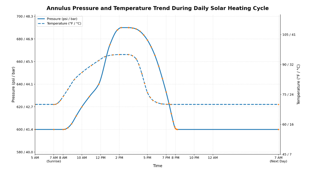
This effect is generally more pronounced in smaller IITs, particularly those ≤ 20 in., due to the reduced annulus volume. To mitigate pressure fluctuation in such cases, a dummy pigging module may be installed within the annulus to increase the enclosed volume. In some applications, a pressure accumulator may also be incorporated for the same purpose. FIG. 34 illustrates a tool configured with a dummy pig module in the annulus.

Annulus monitoring
After the tool has been set and the hold period has commenced, the annulus pressure is monitored for a predetermined duration, typically 4 hrs, although the required period may vary depending on project requirements. During this monitoring phase, if the high-pressure plug seal leaks, the annulus pressure will increase. Any such pressure rise is detected by the system and communicated to the plug operator through the control software interface (FIG. 35).

The same principle applies to the low-pressure plug. If the low-pressure seal does not maintain integrity, the annulus pressure will decrease and the condition will be detected and reported to the plug operator. In such cases, the tool is unset, repositioned a short distance upstream or downstream, and the setting procedure is repeated. The tool is then retested, and if isolation performance is confirmed, an isolation certificate is issued to the client, after which pipework may commence (FIG. 36).

During the isolation period, the tool remains under continuous monitoring. An annulus pressure alert function is activated within the CM, and a project-specific pressure envelope is defined within the software. The tool then performs periodic monitoring at predetermined intervals established in the CM firmware, allowing any deviation from the accepted annulus pressure range to be identified and communicated to the operator.
Unsetting process
After completion of the customer work scope and execution of all required documentation, the tool is ready to be unset and pigged either back to the launcher or downstream to the receiver.
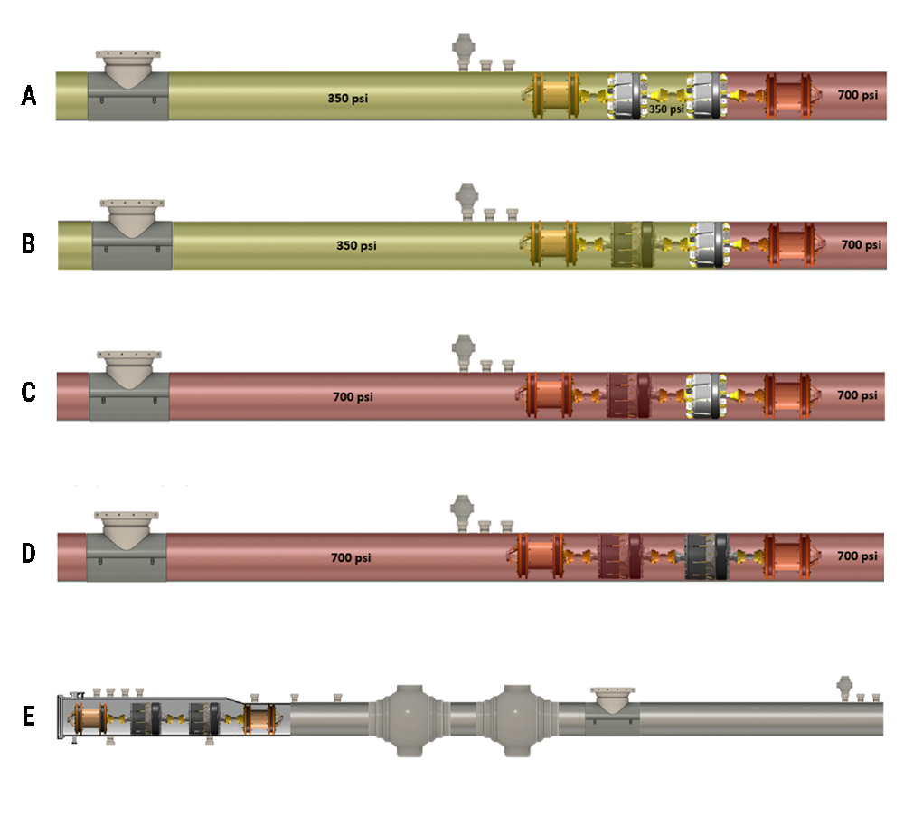
Before unsetting, the low-pressure side is pressurized until it matches the high-pressure side. Once pressure equalization has been achieved, both the low- and high-pressure plugs are instructed to unset.
It is important to emphasize that when the plug is in a self-locking condition, the tool cannot be unset using hydraulic pressure alone. Therefore, if an operator were to accidentally send an unset command while the tool is self-locked, the tool would remain set. The differential forces acting on the plug are greater than the hydraulic force the pump can generate, preventing unintended release and making the isolation system inherently safe (FIGS. 37a–37e).
Tracking
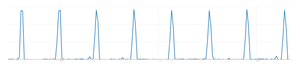
Both the CM and battery module are equipped with tracking capability. The system generates a "ping" signal that can be detected using an external antenna. Each pinger has a unique ID, allowing the operator to identify whether the signal is coming from the CM pinger or the BM pinger.
For precise tool location, the pipe must be exposed in the area where the tool is expected to be located. Under these conditions, typical locating accuracy is less than 1 in. FIG. 38 shows a typical ping.
Sour gas/oil
IITs are not normally intended for direct isolation in pipelines containing high concentrations of hydrogen sulfide (H₂S) without additional engineering assessment and operational planning. Where a project requires isolation in high-H₂S service, the standard approach is typically to batch the isolation tool within a protective liquid slug, such as diesel, glycol, water, seawater or monoethylene glycol (MEG), to reduce direct exposure of the tool to the sour medium during deployment and recovery. This is generally achieved by positioning two or more pigs ahead of and behind the tool to contain the liquid batch (FIG. 39).

Anode protection
If water, seawater or another conductive liquid is used for pigging, and the tool remains submerged during the isolation period, the tool may be exposed to corrosion over time. To mitigate this risk, sacrificial anodes, typically zinc or magnesium, may be attached to the tool to provide supplementary galvanic protection. Although this measure does not eliminate corrosion entirely, it can significantly reduce the corrosion rate and extend tool service life. It is also important to lubricate the piston rod after the isolation has been completed to minimize the risk of further corrosion during transportation and handling.
IIT sizes
Most IIT vendors classify their tool fleets into two general size categories: small tools and large tools. The division typically occurs at 16 in.–20 in., primarily due to the available space and internal volume within the CM required to accommodate the necessary system components. With larger tools, greater hydraulic flow capacity is required to avoid excessive plug-setting times. Extended setting times lead to increased battery consumption, and battery usage is therefore minimized wherever possible. IITs are generally available in sizes ranging from 6 in.–48 in. and above. For smaller tools, one of the principal technical challenges is piggability.
Takeaway
IITs provide a highly engineered and controlled method of pipeline isolation, combining mechanical sealing, hydraulic actuation, electronic monitoring and fail-safe design principles into one integrated system. As described in this part, the tool can be configured in several ways depending on project requirements, with the double block and monitor arrangement being one of the most widely used and highest-integrity configurations.
A key safety feature of the system is the self-locking principle, where pipeline DP helps maintain the isolation without relying solely on continued hydraulic pressure. When combined with annulus monitoring, redundant modules, contingency release functions, structural verification, SIT and FAT, the system provides a robust and verifiable isolation method suitable for critical pipeline intervention work.
The setting and unsetting sequences are carefully controlled to ensure that each PM is activated, monitored, pressure-tested and released in a safe and predictable manner. Annulus pressure monitoring provides direct confirmation of barrier integrity, while pressure and temperature correlation helps distinguish true leakage from normal thermal effects during extended isolation periods.
Additional functions such as ELF communication, tool tracking, sour-service planning, corrosion protection, hydrotest capability and project-specific configurations further demonstrate the flexibility of the IIT platform. These features allow the tool to be adapted to a wide range of pipeline sizes, operating conditions and customer requirements. Overall, the IIT is not simply a mechanical plug, but a complete isolation system designed around safety, control, redundancy and verification.
About the Author
FRANK SOENDERVIK is a pipeline isolation and pigging specialist with extensive hands-on experience in IITs, tool development, field operations and technical project execution. His work focuses on advancing safe and reliable isolation methods for pressurized pipeline systems, including double block and monitor applications, piggable isolation tools, launcher and receiver operations, and control module development.
Soendervik is closely involved in the development of Pipeline Ultraisolation Group's IIT, combining practical field knowledge with engineering-focused problem solving. His experience includes tool testing, operational procedures, pressure monitoring, tracking systems, animation and visualization of tool sequences, and technical communication for customers and industry stakeholders.
Through his articles and technical content, Soendervik aims to make complex pipeline isolation concepts easier to understand for operators, engineers, project teams and the broader public. His goal is to help improve awareness of how modern IITs work, how they are tested and how they can support safer pipeline maintenance and modification work.